Overview
The Rechargeable Battery Asset Tracker allows you to monitor the location of stationary and non-stationary assets within Fleet Pro. Follow the instructions in this guide to install the Asset Tracker in the asset.
Who uses this feature
Fleet Managers, Dispatch Managers, and Dispatchers
Applies to all business types
Feature configuration
To get started with Fleet Pro, request a demo by clicking Get Started on our Pro Products page, or reach out to your Customer Success Manager (CSM) or Pro Account Manager.
Things to know
Take note of the serial number printed on the device. This serial is required later when you're setting up your Fleet Pro.
Azuga is Fleet Pro's hardware provider.
What's in the box
Rechargeable Asset Tracker |
Package includes Asset Tracker |
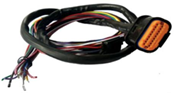
18-pin Harness |
|
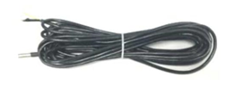
Temperature Sensor |
|
Note: Hardware in the box may vary according to your requirements.
Primary Connections
Definition | Description | Wire Connector | Pin |
|---|---|---|---|
Power | Primary Power (8-32V) | Red | 1 |
AGND (Analogue ground) | Primary ground | Black | 3 |
Ignition | Ignition Detection Input, Positive Trigger | White | 5 |
1-wire | Temperature sensor input | Grey | 9 |
For tracking purposes, connect the Red wire to the Primary Power and Black to the Ground.
Note: The main color of the dual color cable is the first one. For example, Black/White means black is the main color and white is the secondary color.
Installation - Asset Tracker
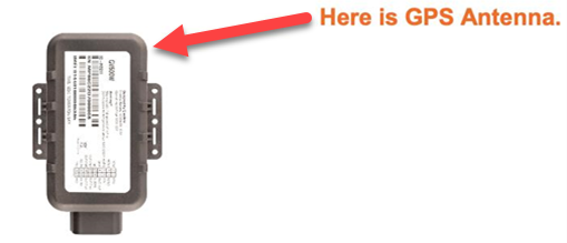
Ensure the side with the antenna is facing towards the sky with a clear line of sight to have better signal reception.
Firmly install the device to a reliable surface to prevent it from falling off.
Do not install the device under a metal surface or in enclosed environments that would have difficulty getting GPS and network signals.
Determine an appropriate location on the asset to mount the device. Ensure that the asset tracker is placed with the top surface facing towards the open sky.
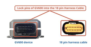
The GV600 device must have an unobstructed view of the sky.
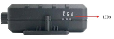
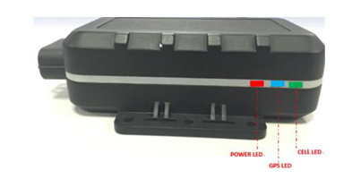
The location of the device must be such that the lights from the status LEDs are easily visible.
Install the screws in front.
Connect the wires to appropriate power sources.
The power input (Red wire) must be connected to a constant +12V or +24V power supply.
The ground line (Black wire) must be connected to chassis ground.
Observe the following LED sequence once installed:
LED Type
LED Status
Device Status
Cell LED (Green)
Slow Flashing
Device has registered to Cellular network
GPS LED (Blue)
On
GPS chip has got GPS info
Power LED (Red)
Fast Flashing
External power in and internal power charging
On
External power in and internal power fully charged
Once the device is activated, you can navigate to the Asset Data section of Fleet Pro to confirm the GPS ping is displaying on the Live Map.
Note: It may take several hours for the GPS ping to display.
Set up Fleet Pro
After you've installed your hardware, you need to match them to your vehicles and drivers in ServiceTitan.
To access Fleet Pro, go to the navigation bar and click Fleet Pro
 .
.Go to the Asset Data screen. There should be a list of 10 digit numbers in the GPS Device Serial # column which represents the serial numbers of your installed devices.
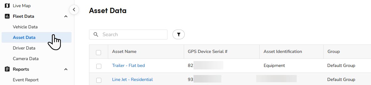
Click one of the serial numbers listed under the Asset Name column.
On the Asset Details screen that opens, click the Asset Name to assign a name to the Asset. This will be the name that appears on the Live Map.
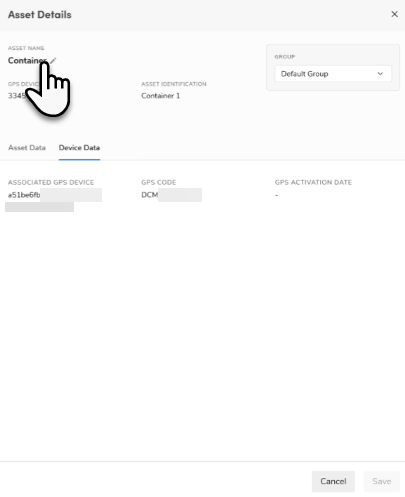
When finished, click Save.
Want to learn more?
See Fleet Pro