Overview
The Fleet Pro View StandardCam works in conjunction with a Plug-and-Play GPS Tracker in the vehicle. It provides the driving data needed to use Fleet Pro. Follow the instructions in this guide to install the OBD-II and StandardCam in the vehicle.
Who uses this feature
Fleet managers, dispatch managers, and dispatchers
Applies to all business types
Things to know
Azuga is Fleet Pro's hardware provider.
Take note of the serial number printed on the device. This serial is required later when you're setting up your Fleet Pro.
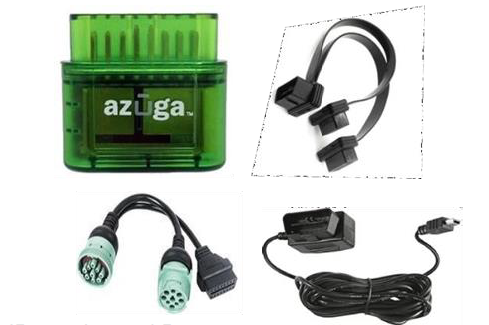
What's in the box
OBD-II OBD Y-Cable JBus Y-Cable Power Cable |
JBus color and Pin may vary from the one shown here. |
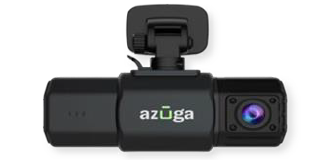
StandardCam |
|
Mirror mount holder |
|
Installation - OBD-II
The OBD-II or JBus device plugs into the vehicle's diagnostic port; the cable attached receives the digital input (ON/OFF) and transmits it to the device that reports to Fleet Pro. The OBD-II device can be installed with Port Exposed or Port Occupied.
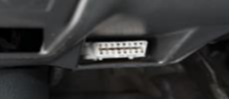
Port Exposed
Locate the vehicle's diagnostic port. It can typically be found below the steering wheel. Follow the below steps to install the OBD-II:
Exposed Port |
Port with Panel |
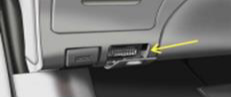
Turn off the vehicle or the unit on which the installation is performed.
Plug the GPS device into the diagnostic port directly if the port is exposed.
If the port is covered by a panel or door, use the extension cable to install the OBD device.
Note: Make sure the OBD device is not protruding from the panel.
LED lights on the GPS device should start flashing.
Make sure the green LED light flashes for five seconds. This indicates the device is ready to use.
If the red LED blinks, the installation failed. Remove the GPS device and repeat steps 1–5.
Port Occupied
If the diagnostic port is already occupied with another device, use the Y-cable to install the GPS device:
Remove the other device from the diagnostic port.
Plug in the female end of the Y-cable into the port.
Connect the GPS device to one end of the Y-cable.
Connect the removed device from step 1 to the other end of the Y-cable to complete the installation.
Make sure the green LED lights on the GPS device flash for five seconds. This indicates the device is ready to use.
If the red LED blinks, the installation failed. Remove the device and repeat steps 1–5.
Installation - StandardCam
StandardCam and OBD devices are generally paired and shipped together.
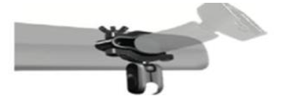
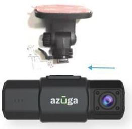
Option 1: Mirror mount (recommended)
Insert one screw into the slot of the lower half of the clip and install the silicone rubber pad.
Mount the upper half of the clip and tighten the screw with the butterfly nut.
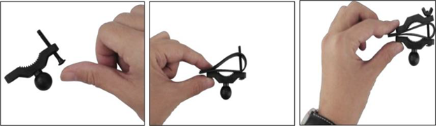
Install the other screw and mount the clip on the rear-view mirror of the vehicle.
Tighten the clip using the butterfly nut.
Mount the clamp to the attached clip.
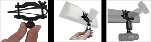
As the mount is installed on the rear-view mirror, take the connector and attach one end of it to the mount.
Insert the StandardCam into the other end of the connector.
Option 2: 3M mount tape
Clean the mounting location with the provided alcohol wipes.
Make sure the mounting location is clean and dust-free. Make sure the installation is performed under a moderate temperature.
Take the mount and insert the holder into the StandardCam.
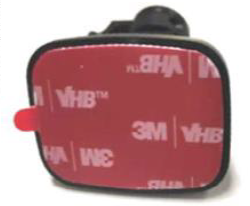
Peel off the 3M tape cover.
Stick the mount with the StandardCam as high as possible on the driver side of the windshield.
Note: The installed StandardCam should not obstruct the driver's view.
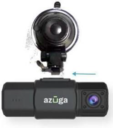
Option 3: Suction mount holder
Clean the mounting location with the provided alcohol wipes.
Make sure the mounting location is clean and dust-free.
Take the suction mount holder and insert it in the slot in the StandardCam.
Stick the mount with the StandardCam as high as possible on the driver side of the windshield.
Note: The installed StandardCam should not obstruct the driver's view.
Powering StandardCam AI
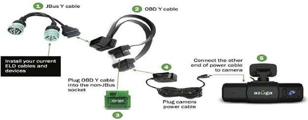
Option 1: OBD-II power cable
Plug the Y-cable into the OBD port of the vehicle. Determine the best possible way to route the power cable of the camera to avoid any obstruction to the driver:
In many cases, the power cable can be tucked under the headliner gently by using the included orange installation lever.
You can use the adhesive cable holders to route the power cable along the top of the windshield to prevent obstruction to the driver's view.
The power cable can be routed along the weather strip on the A-pillar of the vehicle or under the dash.
The power cable can be run under the driver floor mat and plugged into one end of the Y-cable to the OBD-II device.
Option 2: Hardwired
To use the StandardCam AI Camera's complete set of features, such as active standby, you need to connect the camera to a constant 12V power source. This installation requires you to have a hardwired kit that is sent along with the camera.
Locate the fuse box: Check the car's owner manual for the fuse box location. It may vary depending on the vehicle model. Remove the plastic panel to access the fuse box. It may open by simply lifting a tab and pulling it with your fingers, or you may need a trimming tool.
Use the correct slot: Use a circuit tester to test which fuse is constant (typically red). A fuse that is constant stays on when the car is off. The camera automatically enters standby mode when the car is not moving for 10 minutes.
Connect the red wire to the ignition line: Generally, vehicle fuses may have power at all times (always hot), or only when the vehicle is running (hot at start). In order to have the camera turned on automatically when the vehicle is running, and turned off when the driver turns off the vehicle, you need to connect a circuit kit to a hot start fuse. To identify which fuses are hot at start, it is recommended that you use a simple circuit tester that shows when power is present.
Ground the hardwire kit: The ground wire is usually either ring or C-shaped. Connect the ground wire by slipping it under a metal bolt or a screw in your vehicle. You may need a socket wrench set to loosen the bolt. Loosen the bolt enough to slip the ground wire in and then tighten the bolt again. A loose ground can result in power issues for your camera. It is recommended that you ground your wire to an unpainted bare metal bolt.
Option 3: Cigarette Lighter Adapter (CLA)
Plug one end of the USB cable into the StandardCam.
Route the StandardCam power cable using the provided tool and adhesive cable holders.
Plug the other end of the USB cable into the CLA.
Step 5: Set up Fleet Pro
After you've installed your hardware, you need to match the hardware to your vehicles and drivers in ServiceTitan:
Go to the navigation bar in ServiceTitan and click Fleet Pro
 .
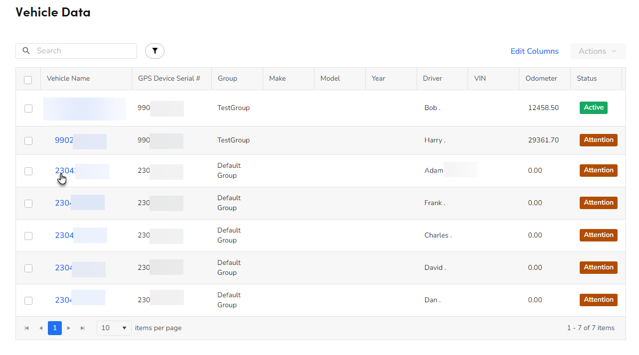
.Click Vehicle Data. There should be a list of 10 digit numbers in the Vehicle Name column which represent the serial numbers of your installed devices.
Click one of the serial numbers listed under the Vehicle Name column.
Note: At this point, you need to reference the notes you recorded regarding which device was installed in which vehicle.
On the Vehicle Details screen that opens, click the Assigned Vehicle dropdown. This selection pairs the device data with the truck you've specified.
Note: Trucks in this list are pulled from Settings
 > Trucks & Warehouses. If you don't see a truck that you need to pair with a device, you can add it there.
Click the Assigned Driver dropdown and assign a driver to the vehicle you chose in step 4.
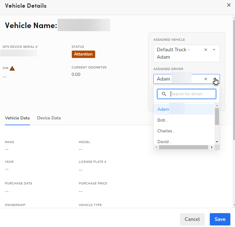
The Status transitions to Active.

Review and fill out the editable fields in the Vehicle Data section. These details are necessary to use alerts and events in Fleet Pro.
When finished, click Save.
Repeat these steps for the rest of your installed devices.
Want to learn more?
See Fleet Pro